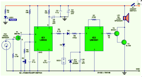
Here is the circuit design of vibration sensor alarm Initially, when the power switch S1 is turned to the "on"
Here is the circuit design of vibration sensor alarm. Initially, when the power switch S1 is turned to the "on" position, the power indicator LED1 immediately lights up. Iclm555 (IC1) is connected as a simple latch circuit with control input. When powered on, RC components R4 and C5 connected to its reset pin 4 force the latch to enter standby mode (low-level invalid output). The circuit is driven into sleep mode.
Once vibration is detected, mosfett1 is triggered by the forward pulse output of the vibration sensing mechanism built around the piezoelectric ceramic chip and related components. Therefore, control input pins 2 and 6 of the IC1 latch are grounded. Output pin 3 of IC1 is now high. The positive power supply of output pin 3 of IC1 extends to the three tone alarm generator um3561 (IC2) through R5, D1 and R6. Elements R6 and zd1 stabilize the input power supply of IC2 at about 3.3V. The output signal of IC2 is amplified by Darlington to transistors T2 and T3, and an alarm sound (siren sound) is generated through speaker LS1.
The reset switch S1 can be used to turn off the alarm sound by resetting the latch circuit. For safety, S1 and S2 use key lock switches. A relay can also be connected at the output socket (SOC1) of the circuit to supply power for high-power beacons, emergency alarms and fence electrification devices.
The alarm circuit of intelligent vibration sensor is powered by 9V DC power supply. The compact pp3-/6f22 alkaline battery can be used to power the circuit.
Contact Information
E-mail:
Fax:
Address:402-410, Minle science and technology building, Minle science and Technology Park, Meiban Avenue, Longhua District, Shenzhen